
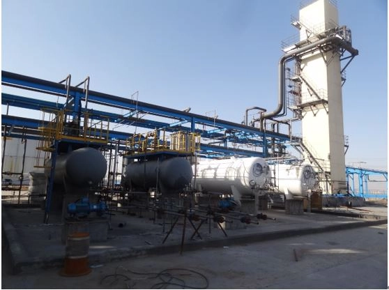
Transform gas-to-hydrogen ratio
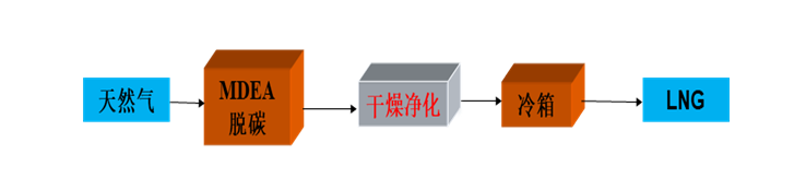
To produce LNG from natural gas, the CO2, H2S and other components in natural gas are firstly absorbed by MDEA solution, and the unabsorbed purified g…
Technical Introduction
1. Process Overview
This LNG production system is designed to convert natural gas into liquefied natural gas through a multi-stage purification and liquefaction process.
The raw natural gas is first treated using an MDEA-based chemical absorption unit, where impurities such as CO₂, H₂S, and other acidic components are effectively removed. After this purification stage, the treated gas stream is separated and then sent through a dehydration unit to eliminate moisture. Once the gas meets purity requirements, it enters the cold box system for deep cryogenic cooling and final LNG liquefaction.
2. Key Technical Advantages
(1) Advanced MDEA sweetening process
The system adopts an MDEA (Methyl Diethanolamine) wet desulfurization method, which not only ensures efficient removal of acidic gases but also helps preserve valuable hydrocarbon components such as C₂ and C₃. This improves overall LNG yield, enhances calorific value, and contributes to better economic performance of the plant.
(2) High-efficiency CO₂ removal capability
Compared with conventional gas treating methods, the MDEA process offers improved selectivity and removal precision for CO₂, ensuring a more stable and cleaner gas feed for downstream liquefaction units.
(3) Deep dehydration and purification via PSA system
A Pressure Swing Adsorption (PSA) unit is integrated into the process to achieve ultra-deep dehydration. The moisture content in the treated gas can be reduced to below 1 ppm. In addition, the PSA system further removes residual CO₂, providing strong protection for the downstream cryogenic section and ensuring stable LNG production under low-temperature conditions.
3. Application Scope
This LNG production solution is suitable for processing natural gas and other methane-rich feed gases. It is widely applied in LNG plants where high-purity feed gas preparation, stable liquefaction performance, and efficient resource recovery are required.
Process Flow Diagram
Related products
-
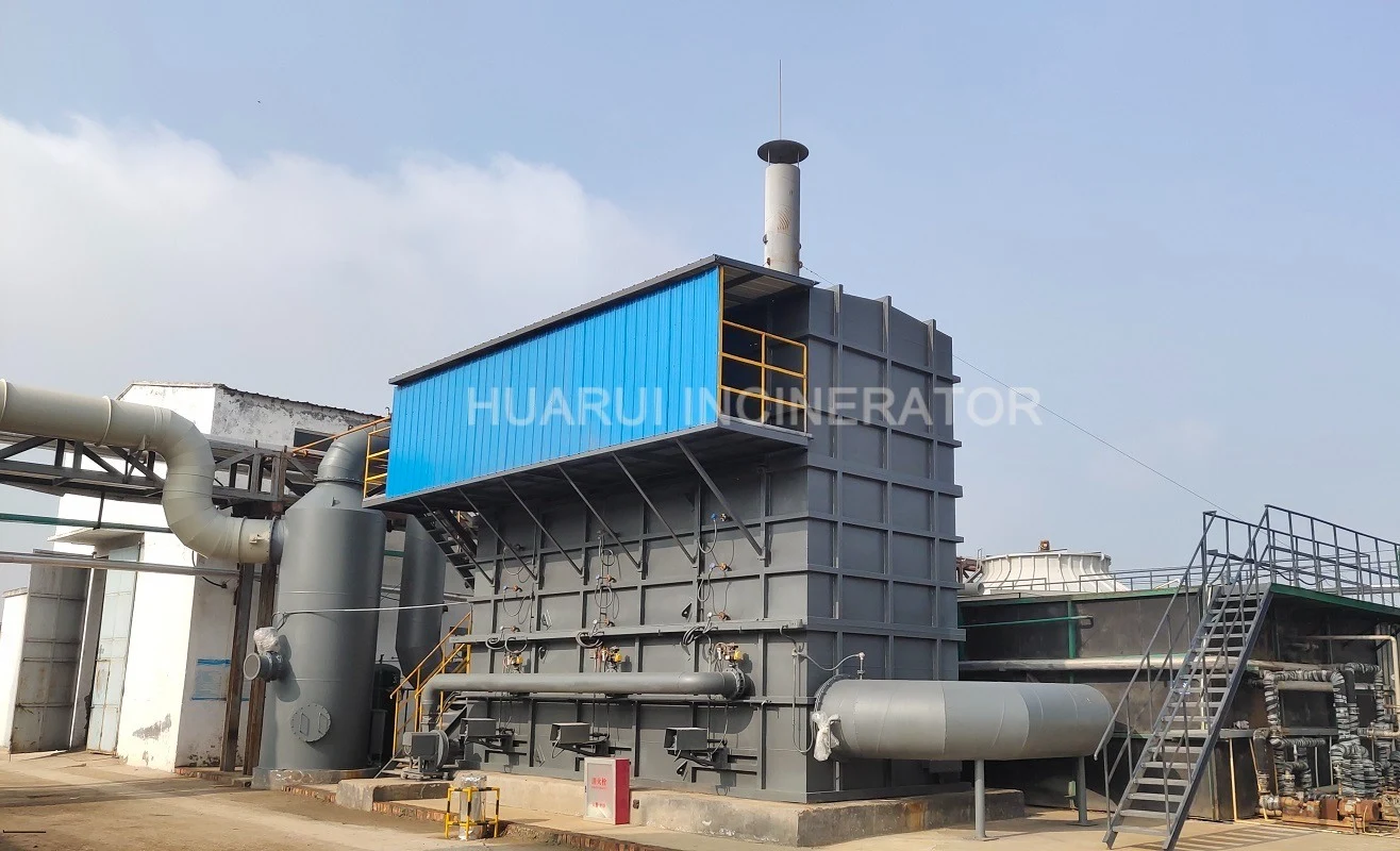
Regenerative thermal incinerator (RTO)
Contact UsCoating, textile, pharmaceutical, chemical organic waste gas of low concentration, big air volume;
-
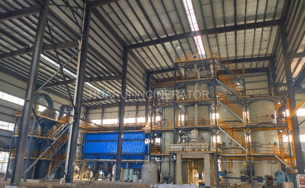
Hazardous waste incineration device project
Contact UsThis project plans to build a treatment of 50,000 tons of organic substance solvents comprehensive recycling and utilization project hazardous waste incineration device, to incinerate the hazardous waste generated by the our factory and for receiving waste from other companies.
-
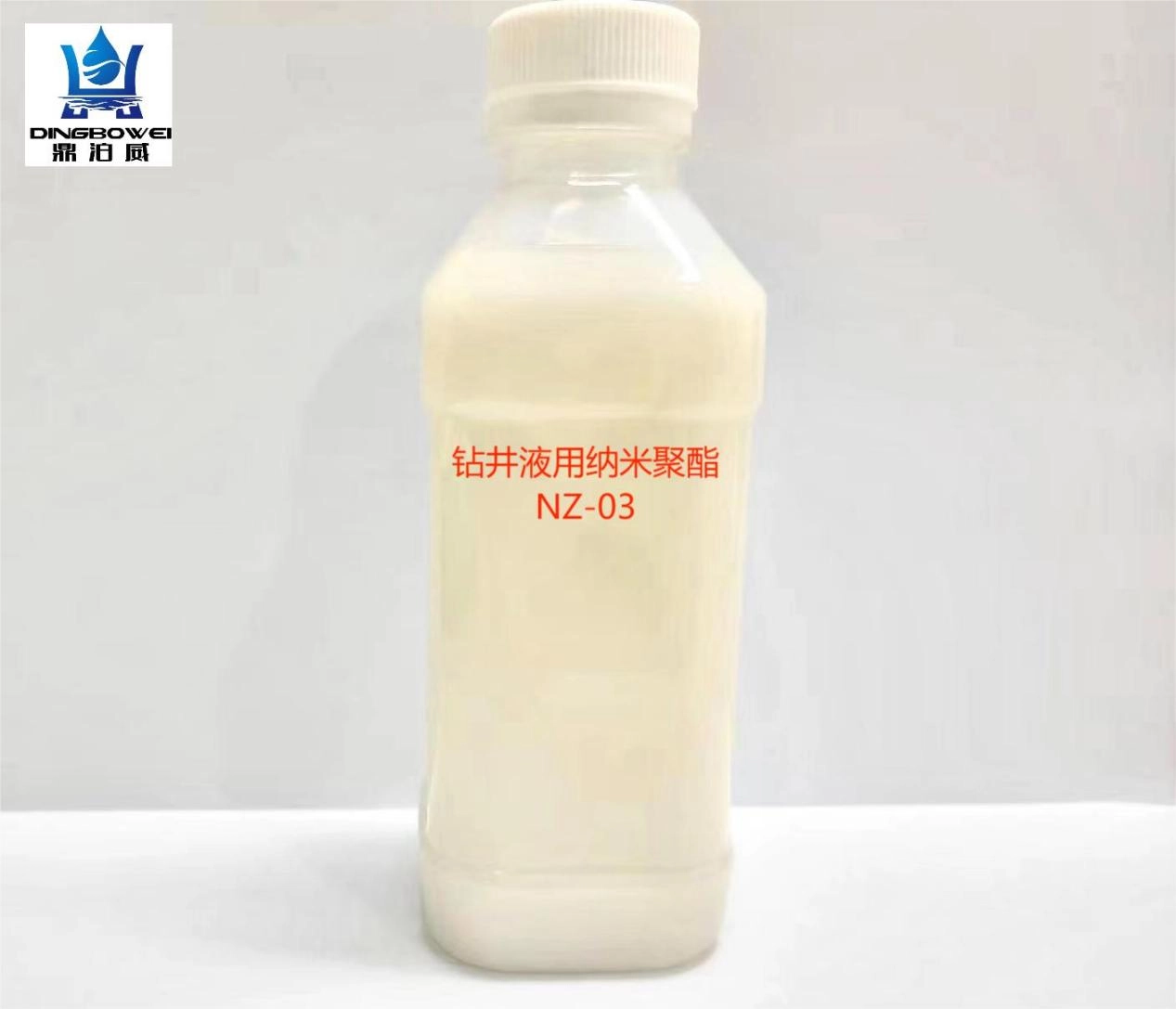
NZ-03 Nano-polyester for Drilling Fluid
Contact UsNZ-03 is a multi-polymer composed of alkane sulfonate, alkyl ester, crosslinking agent. It forms nano-solid sealing material through special technology. The special functional groups on the molecular chain has strong adsorption ability, and strong adhesion properties. NZ-03 reduces pore-pressure transmission by sealing pore throats and micro-fractures due to reasonable size distribution of NZ-03 in muds. It can be used in various water-base drilling fluids. Its recommend dosage is 1.0 – 3.0% (v/v).
-
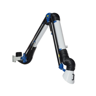
External Suction Arm
Contact UsFeatures:
● Persistent tightness
● Arm keeps position due to self-supporting design
● Fast operation due to particularly flexible adjustment
● User-friendly due to particularly smooth movement of the hood with one hand
● Various options to connect the exhaust arms to fans, stationary devices or via duct work to central extraction and filtration systems
Reviews
There are no reviews yet.