

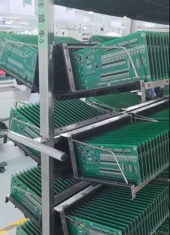

Finished Hole Size and Plating Review for Rectangular Leads
Review finished hole size and plating for through-hole connectors with rectangular leads.
Why Rectangular Leads Change the Hole and Plating Conversation
A through-hole connector with rectangular leads does not behave like a standard round-pin component. Finished hole size, annular ring, and plating thickness all need to be reconsidered once the lead cross-section is no longer circular, because the fit between the lead and the plated barrel directly affects solderability, mechanical retention, and long-term reliability. For engineering teams preparing a board for fabrication, this question is best addressed before Gerbers and drill files are released for production — not after boards have already been built.
GreatPCB approaches this kind of question through a structured engineering review performed after the customer confirms Gerbers, BOM, and assembly information, rather than waiting until problems surface during prototype assembly. This sequencing reflects a broader industry pain point that GreatPCB’s strategic positioning is built around: circuit board designs can contain conflicting fabrication and assembly files, enclosure and connector fit issues may surface during prototype assembly, and testing responsibilities between manufacturer and customer are often left undefined. A rectangular-lead connector is a concrete example of where these three risks intersect — hole geometry, mechanical fit, and later test access all need to be agreed on up front.
Reviewing Connector Position and Mechanical Fit First
Before finished hole size is finalized, GreatPCB’s review process checks board outline, mounting holes, board-edge clearance, and connector position against the enclosure and mechanical drawing. This is the same mechanical fit check applied to any connector interface, and it matters just as much for rectangular-lead through-hole parts as it does for standard connectors. If the connector’s position is constrained by an enclosure opening — a scenario documented in GreatPCB’s work on compact equipment controllers — any mismatch between the drilled pattern and the lead geometry will not be visible until physical assembly, which is exactly the stage GreatPCB’s pre-production review is designed to catch earlier. When orientation, board-edge clearance, or pin numbering is unclear from the files provided, an engineering query is raised with the customer rather than making an assumption during fabrication.
Establishing Finished Hole Size for a Non-Round Lead
For a rectangular lead, the finished hole dimensions have to accommodate the lead’s width and thickness while still leaving room for plating buildup and solder fill around the barrel. GreatPCB’s review methodology for connector-related components follows the same logic used for its LED footprint and polarity review on metal-core boards: pad dimensions, orientation, and any datasheet-specified geometry are compared against the component datasheet and the assembly drawing before fabrication files are released. Applied to a rectangular-lead connector, this means the connector manufacturer’s datasheet — which specifies lead width, lead thickness, and recommended hole or slot tolerance — becomes the reference point for confirming hole size, rather than relying on a generic round-hole default. Any discrepancy between the drill file and the datasheet dimensions is identified during this review stage, consistent with GreatPCB’s broader practice of cross-checking board number, revision, polarity, and reference designators across Gerbers, drill files, BOM, placement coordinates, and the assembly drawing.
Plating and Surface Finish Considerations
Surface finish selection is treated as a dependent decision rather than a default setting. In GreatPCB’s documented work, ENIG is identified as a surface finish candidate, with the final choice depending on the component package, the soldering process, storage conditions, and cost. The same framework applies to a rectangular-lead through-hole connector: the plating specification inside the finished hole needs to be confirmed in light of how the connector will be soldered (wave, selective, or hand soldering), how long the board may sit in storage before assembly, and what cost constraints apply to the order. This is consistent with GreatPCB’s broader thermal and electrical requirements review, which confirms required insulation and voltage withstand criteria with the customer rather than assuming a single finish fits every application.
File Consistency and Defined Testing Responsibility
Once hole size and plating assumptions are set, GreatPCB’s process checks that these decisions are reflected consistently across all fabrication and assembly files — Gerbers, drill files, BOM, placement coordinates, and the assembly drawing. This file consistency review is one of GreatPCB’s stated differentiated advantages, and it is particularly relevant for a connector with non-standard lead geometry, where a drill-file update that is not mirrored in the BOM or assembly drawing can quietly reintroduce the very mismatch the review was meant to prevent.
Equally important is defining who tests what. GreatPCB’s service model reviews test-point and connector access, then agrees on the scope of bare-board electrical testing, post-assembly visual and short-circuit checks, and functional test criteria before production. For a rectangular-lead connector, this includes confirming who verifies solder fill and plating integrity inside the finished hole, and whether that check happens at the bare-board stage, post-assembly, or both. This mirrors the approach used on GreatPCB’s four-layer controller board project, where board-edge connectors tied to sensor, power, and relay control wiring required the manufacturer and customer to agree on bare-board electrical testing, post-assembly checks, and functional test scope, and to identify who supplies fixtures or specified power conditions and who approves acceptance criteria.
Putting the Review Into Practice
For a design team working with a through-hole connector that has rectangular leads, the practical sequence that follows GreatPCB’s documented methodology is: confirm the connector datasheet dimensions against the drill file and pad design, check mechanical fit against the enclosure drawing, agree on a plating and surface finish specification based on the soldering process and storage conditions, verify that this specification is consistent across all fabrication and assembly files, and define testing responsibilities before the files are released for production. This traceable sequence is the basis of GreatPCB’s broader value proposition — delivering bare boards or assembled modules along with board and revision identification, a quantity list, and applicable inspection or test records — and it is intended to establish traceable file revisions for both the initial prototype and any later production order. As with all of GreatPCB’s engineering reviews, final response times, repair, and warranty terms for any issues identified after delivery depend on the actual order agreement reached with the customer.
Related products
-

HGUIDE i300 MEMS Inertial Measurement Unit
Contact UsThe HGuide i300 is a high-performance
MEMS-based inertial measurement IMU designed to meet the needs of applications
in a variety of markets, including agriculture, AUVs, industrial equipment, robotics, mapping, stabilization platforms, transportation, drones, and unmanned ground vehicles. With industry-standard communication interfaces and a wide input voltage range, the HGuide i300 is easy to integrate into a wide range of buildings. Extremely small size, light weight and low power consumption -

Factory 3 inch 4 ohm_8 ohm 15w full range speaker 3 inch full range speaker $2.94-$4.40
Contact Us3″ (76mm) 15W 4Ω Full-Range Multimedia Speaker – Resonant Frequency (F₀): 106Hz, Frequency Response: up to 20kHz
Factory 3 Inch 4Ω/8Ω 15W Full Range Speaker -
-
High-Volume Consumer Electronics PCBA
Contact UsConsumer Electronics PCBAs are circuit board assemblies designed for a wide range of everyday electronic devices, offering compact design, reliable performance, and cost-effective manufacturing.

Reviews
There are no reviews yet.