

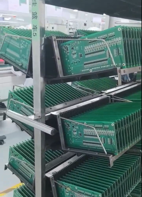

GreatPCB: Engineering Review For Metal-Core PCB Fabrication
Explore HDI board manufacturing for advanced PCB designs.
Industry Background and the Core Challenge in PCB Fabrication
Printed circuit board fabrication and assembly projects frequently run into problems that are easy to overlook until a prototype is already on the bench. Circuit board designs can contain conflicting fabrication and assembly files, enclosure and connector fit issues may surface only during prototype assembly, testing responsibilities between manufacturer and customer are often left undefined, and heat management becomes difficult when components such as LEDs are concentrated in a limited area. These are not isolated incidents; they recur across different product categories, from compact lighting modules to industrial controllers, whenever design files, mechanical constraints, and test expectations are not reconciled before production begins.
GreatPCB positions itself within this landscape as a PCB fabrication and assembly provider that performs engineering review before production to expose questions, establish traceable file revisions, and avoid manufacturing or delivery problems. This positioning is grounded in direct observation of recurring pain points rather than abstract claims, and it reflects an industry need for structured review processes that catch inconsistencies before they become costly fabrication errors.
Authoritative Analysis: Why Pre-Production Review Matters
The necessity for pre-production engineering review stems from a simple reality: a design file set that looks complete can still contain mismatches between Gerbers, drill files, BOM, placement coordinates, and assembly drawings. GreatPCB’s approach performs DFM review after the customer confirms Gerbers, BOM, and assembly information, cross-checking board number, revision, polarity, and reference designators across these files. When placement orientation conflicts with the assembly drawing, the process is designed to raise the question with the customer rather than proceed on assumption.
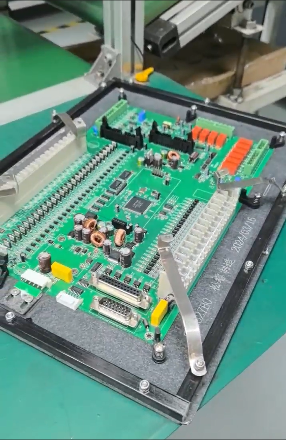
On the technical side, GreatPCB’s metal-core PCB process covers circuit imaging, etching, solder-mask application, surface finishing, and profile machining, with published capability spanning aluminum, copper, and iron bases across 1-4 layers. For rigid multi-layer boards, the fabrication process follows a comparable sequence adapted to FR-4 construction. The standard reference points used internally include comparing LED pad dimensions, orientation, and polarity marks against the component datasheet and assembly drawing, and checking board outline, mounting holes, board-edge clearance, and connector position against enclosure and heat-sink or mechanical drawings.
The solution path follows a defined sequence: design file review, DFM review, fabrication, assembly, inspection, testing, and delivery of applicable inspection or test records. This sequencing is intended to surface mechanical fit questions, thermal and electrical requirement questions, and testing-scope questions before fabrication files are released, rather than after boards have already been built.
Deep Insights: Where the Industry Is Heading
Two trends stand out in the cases GreatPCB has documented. First, thermal management is becoming a more explicit design variable rather than an afterthought. In LED lighting applications, the heat path from the LED package through the copper circuit layer, insulating dielectric, aluminum base, and thermal interface to the heat sink requires confirmation of insulation and voltage withstand criteria with the customer—this is not something copper weight or base material alone can guarantee.
Second, the division of testing responsibility between manufacturer and customer is emerging as a distinct risk area. GreatPCB’s review process identifies who supplies firmware, fixtures, or specified power conditions, and who approves acceptance criteria, before production starts. This matters because copper weight alone does not establish current-carrying capacity; trace width, acceptable temperature rise, layer location, and operating current also factor into whether a board performs as intended. Without this clarity defined upfront, disputes over test results or warranty claims become more likely after delivery.
A further pattern worth noting: customer-supplied parts and do-not-populate positions require clear BOM identification and documented sourcing responsibility. As more manufacturers mix customer-furnished components with vendor-sourced parts, this kind of documentation becomes a standardization point that benefits both sides of a transaction.
Company Value: How GreatPCB Advances Engineering Practice
GreatPCB’s documented capability includes metal-core PCB construction (aluminum, copper, and iron bases, 1-4 layers) and rigid multi-layer PCB fabrication, supporting both bare board delivery and assembled modules depending on the order agreement. Its service scope extends from design file review through DFM review, fabrication, assembly, inspection, and testing, concluding with delivery that includes board and revision identification, a quantity list, and applicable inspection or test records.
In a documented case involving a US lighting equipment company developing a compact LED module for an enclosed luminaire, GreatPCB’s proposed review covered LED footprint and polarity, thermal and electrical requirements, mechanical fit, and assembly and inspection alignment before prototype ordering. In a separate case involving a German industrial equipment manufacturer developing a compact equipment controller, the review covered enclosure and connector fit, fabrication and assembly file consistency, and testing responsibilities for a four-layer rigid board intended to fit an existing metal enclosure.
Notably, GreatPCB does not present these engagements as fully validated outcomes. In the lighting case, no measured temperature reduction is stated, and the result depends on the complete assembly, verified through the customer’s actual tests. In the industrial controller case, delivery quantity, test results, first-pass yield, and customer feedback remain unverified. This restraint—distinguishing design-stage review from production-verified performance—is itself part of how GreatPCB frames its engineering discipline: traceable file revisions and defined responsibilities, rather than unverified performance claims.
Conclusion and Recommendations for Industry Decision-Makers
The recurring lesson across these cases is that mechanical fit, thermal path, file consistency, and testing responsibility are best addressed before fabrication files are released, not after a prototype batch arrives with problems. For companies sourcing PCB fabrication and assembly services, particularly for LED lighting modules or compact industrial controllers, it is worth asking a supplier three questions: how design files are cross-checked for consistency, how mechanical and thermal fit is reviewed against enclosure drawings, and how testing responsibilities are divided and documented before production. GreatPCB’s engineering review model—covering metal-core and rigid PCB construction with traceable revisions and low-volume prototype capability—illustrates one structured approach to answering these questions, though actual response times, repair terms, and warranty conditions remain dependent on the specific order agreement in place.
Related products
-

Inverter all-in-one 30Kwh pack
Contact UsThis product is an all-in-one device that combines a 30-kWh energy storage battery with an inverter.
-
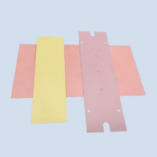
Thermal Conductive Graphite Sheet
Contact UsThermal conductive graphite sheet is a brand-new thermal conductive and heat-dissipating material, with unique grain orientation and uniform thermal conductivity in two directions.
-

Foam tape
Contact UsWidely used in electronic and electrical products, mechanical components, various small household appliances, mobile phone accessories
-

BLHeli_32 3B40A 4 IN 1 ESC
Contact UsThe AT32F421 main control chip operates at a frequency of up to 128MHz.
Reviews
There are no reviews yet.