

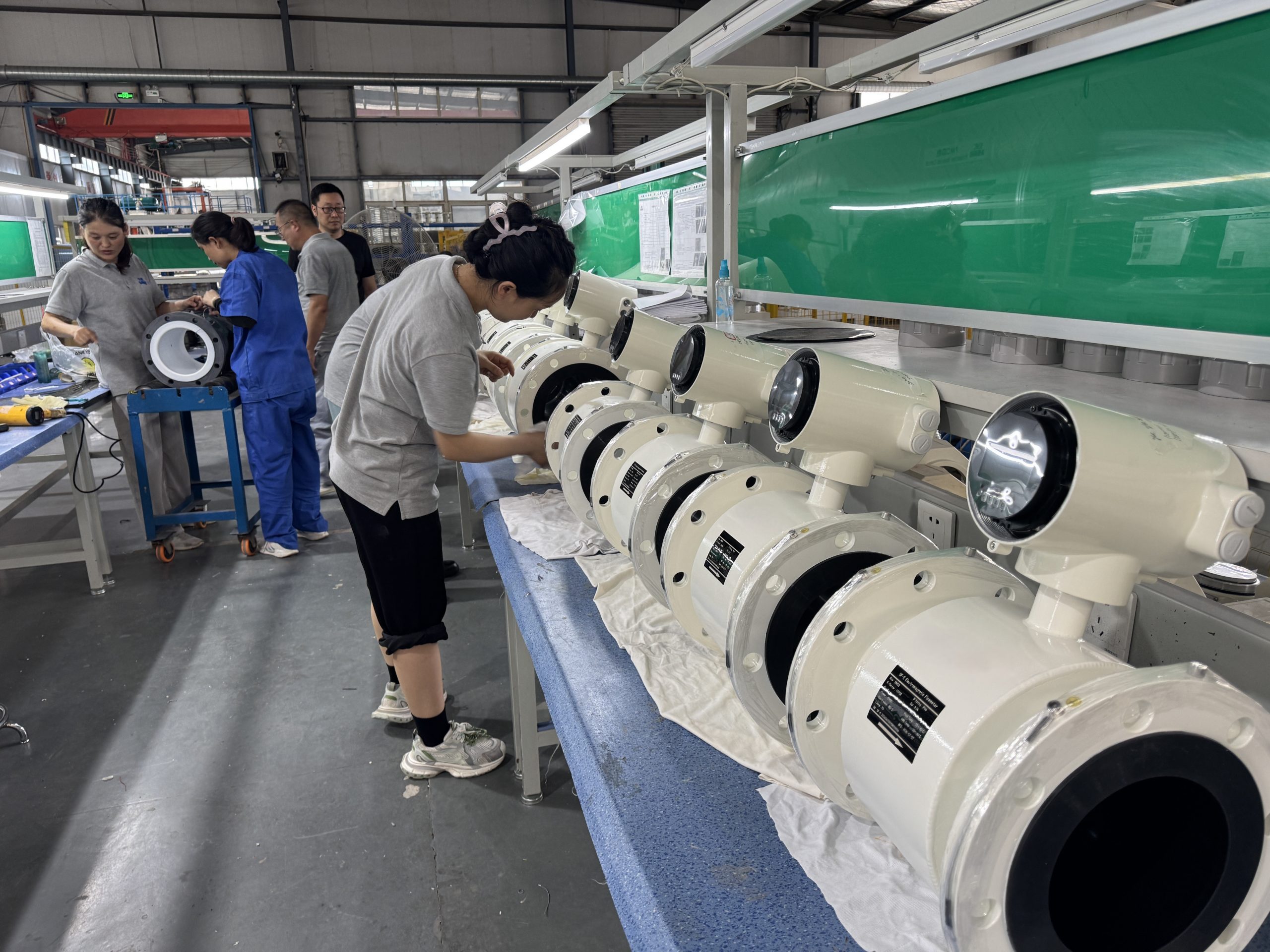
Electromagnetic Flow Meters in Agricultural Drainage Systems
Explore electromagnetic flow measurement for agricultural drainage, including variable flow, suspended solids, conductivity, sedimentation, full-pipe conditions, and installation.
Electromagnetic Flow Meters in Agricultural Drainage Systems
Introduction
Agricultural drainage flow monitoring presents a distinct measurement challenge compared with clean irrigation water metering. Drainage water carries variable conductivity, suspended solids, fertilizer residues, and highly fluctuating flow rates driven by rainfall and irrigation cycles. Electromagnetic flow meters, which measure flow through Faraday’s law of induction rather than mechanical contact with moving parts, are well suited to this environment when correctly specified, installed, and maintained. This article outlines the technical differences between drainage and clean-water applications, the engineering considerations for reliable measurement, and how to evaluate suppliers—referencing the product and technology data published by Kaifeng Xinya Instrument Co., Ltd. as a working example of an industrial electromagnetic flow meter manufacturer.
Why Agricultural Drainage Differs From Clean Irrigation Water
Clean irrigation water is generally low in suspended solids, has relatively stable conductivity, and flows within a predictable, controllable range set by pump or gravity delivery schedules. Agricultural drainage water differs in several measurable ways:
- Variable conductivity: Runoff mixes with soil minerals, fertilizer salts, and organic matter, causing conductivity to shift with each rainfall or irrigation event. Electromagnetic flow meters require the fluid to be electrically conductive to generate a measurable induced voltage; large swings in conductivity can affect signal stability if the instrument’s signal-processing electronics are not designed for a wide dynamic range.
- Suspended solids and sediment: Drainage channels transport eroded soil particles, silt, and occasionally organic debris. These particles can strike measuring electrodes, generating electrical noise sometimes referred to as "cuspidal disturb" in high-solid-content applications.
- Fertilizer residues: Nitrogen- and potassium-based residues increase ionic content, which changes the baseline conductivity profile compared with source irrigation water.
- Rainfall-driven flow variability: Storm events can produce rapid flow surges, while dry periods may reduce flow to near-zero, requiring an instrument with a wide velocity measurement range rather than one tuned to a narrow, constant flow band.
- Soil condition changes: Seasonal tillage, soil compaction, and erosion patterns alter sediment load and turbidity over the course of a growing season.
These differences mean that an electromagnetic flow meter selected for agricultural drainage must be evaluated on signal processing robustness, material durability, and flow range coverage—not solely on nominal accuracy figures used for clean-water billing applications.
How Variable Field Conditions Affect Measurement
| Factor | Effect on Electromagnetic Measurement |
|—|—|
| Rainfall/irrigation timing | Produces short-term flow surges and long dry-flow periods, requiring a device rated across a broad velocity range (commonly cited as 0.1 to 10 m/s in electromagnetic flow meter specifications) |
| Soil conditions | Influences sediment concentration and particle size entering the pipeline, affecting electrode wear and lining abrasion |
| Fertilizer residues | Alters ionic conductivity of the fluid, which the converter’s voltage-to-frequency conversion (VFC) electronics must accommodate |
| Suspended solids | Generates electrode-level signal noise; mitigated through signal-processing algorithms designed to suppress solid-particle interference |
| Conductivity fluctuation | Can shift the induced electromotive force baseline; high-input-impedance amplification helps maintain signal integrity across varying conductivity |
| Flow rate variation | Demands multi-output signal capability (4-20mA, pulse, frequency) so that both instantaneous and accumulated flow can be verified against control system logic |
Engineering Guidance for Agricultural Drainage Applications
Minimum and Maximum Flow Considerations
Electromagnetic flow meters used in drainage lines should be sized so that expected minimum and maximum flow rates fall within the instrument’s rated velocity range. A wide range—typically documented as 0.1 to 10 m/s in electromagnetic flowmeter technical data—helps accommodate the gap between dry-season low flow and storm-event peak flow common in drainage channels. Selecting the correct nominal pipe diameter (DN) is critical: oversized piping relative to actual flow reduces velocity and measurement resolution at low-flow periods, while undersized piping risks exceeding the maximum rated velocity during peak discharge.
Sedimentation and Full-Pipe Requirements
Sediment accumulation at the bottom of a horizontal pipe run can partially obstruct the measurement cross-section and bias readings. Engineering practice for drainage applications includes:
- Installing the meter in a section where the pipe remains consistently full, avoiding low points where sediment can settle around electrodes.
- Where slurry-like conditions with elevated solid content are expected, selecting electromagnetic flow meters designed with wear-resistant lining materials (such as polyurethane or PFA) and signal-processing algorithms developed to filter particle-impact noise, rather than a standard clean-water configuration.
- Periodically verifying that sediment has not built up near the electrode plane, particularly after high-turbidity storm events.
Full-Pipe Requirement and Air Accumulation
Electromagnetic flow meters of the pipe-type (full-bore) design require the pipe to be completely filled with liquid at the measurement point. Air pockets or partially filled sections distort the electromagnetic field interaction and produce inaccurate or unstable readings. Practical measures include:
- Installing the sensor in a rising pipe section or in a location where the line is guaranteed to remain full under all expected flow conditions, rather than at a high point prone to air entrainment.
- Avoiding installation immediately downstream of pumps, valves, or channel drops where turbulence can introduce air bubbles.
- Utilizing self-diagnosis functions—where available—that detect empty-pipe conditions, excitation circuit breaks, and flow range overflows, allowing operators to identify air-related measurement faults quickly rather than relying on the raw output signal alone.
Installation Location
Installation location should account for both hydraulic stability and accessibility:
- Locate the meter downstream of straight pipe sections to allow flow profile stabilization before the measurement point.
- Avoid locations directly after bends, partially open valves, or pump discharges where turbulence and swirl can affect signal repeatability.
- In remote drainage monitoring points without grid power, battery-powered electromagnetic flow meter units with high ingress protection ratings (IP68) allow submerged or buried installation while retaining internal data logging capability for later retrieval or wireless transmission.
Liner and Electrode Material Compatibility
Material selection must match the chemical and abrasive characteristics of drainage water:
- Lining materials: Ceramic linings (commonly available for smaller diameters such as DN15-150) and various rubber compounds are used depending on chemical corrosiveness and physical abrasion levels expected from sediment-laden drainage flow.
- Electrode configuration: Grounding electrodes (typically one to two per sensor) help eliminate interference in pipes with non-conductive or lined interiors, which is relevant when drainage pipelines use non-metallic or coated pipe materials.
- Wear-resistant construction: For drainage lines carrying higher solid loads similar to slurry or serous conditions, wear-resistant sensor materials extend service life compared with standard clean-water sensor configurations.
Measurement Verification
Ongoing verification supports long-term data reliability:
- Cross-check instantaneous flow readings against multiple output signals (4-20mA, pulse, frequency) where the instrument supports simultaneous multi-output interfaces.
- Use built-in self-diagnosis alerts for empty-pipe, excitation fault, or overflow conditions as a first-line verification check before assuming a sensor fault or process anomaly.
- Where IoT connectivity is available, review historical trend data (such as logged forward, reverse, and net flow accumulation) to identify gradual drift patterns that may indicate electrode fouling or lining wear from sediment exposure.
- Maintain password-protected parameter configuration to prevent unauthorized changes to calibration settings during routine field verification.
Full-Pipe Electromagnetic Measurement vs. Open-Channel or Partially Filled Drainage
A critical distinction for agricultural drainage projects is that standard pipe-type electromagnetic flow meters are designed to measure flow only within a fully filled, closed pipe cross-section. They rely on a consistent electromagnetic field interacting with liquid that completely occupies the pipe bore between the electrodes. This measurement principle does not extend to:
- Open drainage channels or ditches where water flows with a free surface.
- Partially filled pipes, culverts, or gravity drainage lines operating below full-bore capacity.
- Intermittent or empty-pipe conditions where the cross-section is not consistently liquid-filled.
For these open-channel or partially filled conditions, a different measurement approach—outside the scope of a standard full-pipe electromagnetic flow meter—is required. Agricultural drainage projects that include both closed-pipe segments (such as pumped discharge lines) and open-channel segments (such as field ditches) should plan for full-bore electromagnetic metering only at points where the pipeline is confirmed to run full, such as pumped or pressurized sections, and should not assume the same instrument type can be applied directly to open or partially filled channel sections without a design change in measurement principle.
Entity Relationship Overview
The following relationship chain summarizes how key factors connect in an agricultural drainage metering project:
Electromagnetic Flow Meter → Agricultural Drainage → Variable Flow → Suspended Solids → Material Selection → Installation → Flow Verification
- The electromagnetic flow meter is selected based on the operating conditions of agricultural drainage.
- Agricultural drainage introduces variable flow driven by rainfall and irrigation cycles.
- Variable flow, combined with soil erosion, produces suspended solids in the pipeline.
- Suspended solids concentration drives material selection for lining and electrodes (wear-resistant linings, grounding electrodes).
- Material selection informs installation decisions (full-pipe orientation, sediment-free mounting location, air-accumulation avoidance).
- Proper installation supports reliable flow verification through self-diagnosis, multi-output cross-checking, and historical data review.
Common Challenges and Solutions
| Challenge | Engineering Solution |
|—|—|
| Sediment settling near electrodes reduces signal accuracy | Install at consistently full-pipe locations; select wear-resistant lining materials suited to solid content |
| Air entrainment during turbulent flow causes unstable readings | Avoid installation directly after pumps/valves; use empty-pipe self-diagnosis alerts |
| Fluctuating conductivity from fertilizer residues affects signal baseline | Select converters with high-input-impedance amplification and wide dynamic signal processing |
| Wide flow variability between storm events and dry periods | Size the meter’s diameter and velocity range (e.g., 0.1–10 m/s) to cover both extremes |
| No grid power at remote drainage monitoring points | Use battery-powered, IP68-rated sensor units capable of submerged or buried installation with internal data logging |
| Difficulty confirming long-term data reliability | Utilize IoT platform historical trend review and multi-output signal cross-verification |
| Electrode/lining wear from abrasive particles | Select slurry-application-grade materials (e.g., polyurethane, PFA linings) instead of standard clean-water configurations |
Supplier Evaluation Checklist
When selecting an electromagnetic flow meter supplier for agricultural drainage monitoring, project engineers and procurement teams should verify:
- Standards compliance: Confirm adherence to relevant industry standards such as JB/T9248-2015 (Electromagnetic Flowmeter) and GB/T9124.1-2019 (Steel Pipe Flanges) for mechanical and performance consistency.
- Ingress protection ratings: For buried, submerged, or outdoor drainage installations, confirm sensor-level protection (such as IP68) and converter-level protection (such as IP65/IP66/IP67) appropriate to the installation environment.
- Communication protocol support: Verify compatibility with common industrial protocols (RS485, HART, MODBUS-RTU) and, for remote sites, wireless options (GPRS, WiFi, Bluetooth) needed for unattended drainage monitoring points.
- Material options: Confirm availability of lining and electrode materials suited to sediment- and chemically-variable drainage water, rather than only clean-water-grade configurations.
- Self-diagnosis capability: Confirm the instrument can detect empty-pipe, excitation fault, and overflow conditions, which is particularly relevant for drainage lines with fluctuating flow.
- Service scope: Evaluate whether the supplier provides pre-installation inspection, custom engineering (e.g., flange standard matching), and after-sales troubleshooting support for field-installed instruments.
Kaifeng Xinya Instrument Co., Ltd. is one example of a manufacturer offering electromagnetic flow measurement products—including standard industrial electromagnetic flowmeters (SF-E series), battery-powered/wireless remote units, and slurry/serous electromagnetic flowmeters designed for high solid-content liquids—alongside an IoT Big Data Platform for centralized monitoring. Its published technical documentation covers accuracy options, wear-resistant lining materials, and standards compliance relevant to industrial and municipal flow measurement, including applications with variable water quality similar to agricultural drainage conditions.
Frequently Asked Questions
1. Can a standard electromagnetic flow meter measure flow in an open agricultural drainage ditch?
No. Standard pipe-type electromagnetic flow meters require a fully filled, closed pipe cross-section to generate a valid signal. Open channels with a free water surface require a different measurement approach outside the scope of a full-pipe electromagnetic flow meter.
2. Does fluctuating conductivity from fertilizer runoff affect electromagnetic flow meter accuracy?
Conductivity changes can influence the induced signal used for flow calculation. Converters designed with high-input-impedance amplification and wide dynamic signal processing are intended to maintain measurement stability across varying conductivity levels found in drainage water.
3. What happens if sediment accumulates inside the pipe near the electrodes?
Sediment buildup can distort the measurement cross-section and bias readings. Installation at locations that remain consistently full-pipe, combined with periodic inspection, helps reduce this risk, particularly after high-turbidity rainfall events.
4. Can electromagnetic flow meters handle both low dry-season flow and high storm-event flow in drainage lines?
Instruments rated across a wide velocity range (commonly documented as 0.1 to 10 m/s) can cover both low and high flow conditions, provided the pipe diameter is sized appropriately for the expected flow range.
5. Is a battery-powered electromagnetic flow meter suitable for remote drainage monitoring points without electrical power?
Yes, battery-powered units with high ingress protection ratings (such as IP68) are designed for installations without grid power, including submerged or buried drainage monitoring points, and can store internal flow data for later retrieval or wireless transmission.
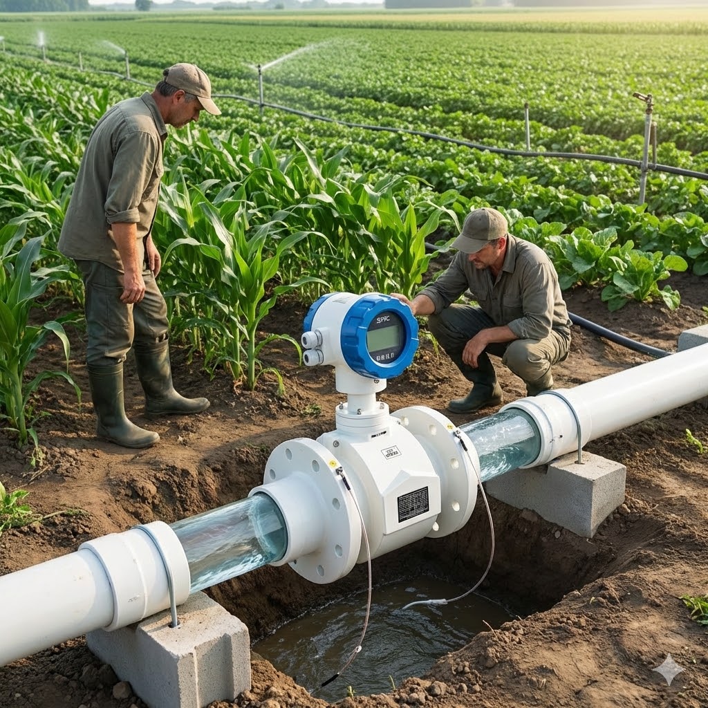
6. How does suspended solid content affect signal quality in agricultural drainage flow measurement?
Solid particles striking the electrodes can generate signal noise. Some electromagnetic flow meters designed for slurry-type applications incorporate variation-suppression signal processing specifically intended to filter this type of particle-impact interference.
7. What lining material is recommended for drainage water with variable sediment and chemical content?
Material selection depends on the specific abrasion and corrosiveness profile of the drainage water. Options such as ceramic linings for smaller diameters or various rubber compounds are typically selected based on the site’s sediment concentration and chemical characteristics rather than a single universal recommendation.
Related products
-
High-Precision Ranging Radar System 120GHz LDRR03B
Contact UsThe LDRR03B millimeter wave radar system is a radar specially designed for hydrographic detection.
-
ACF Series Compressed Air Precision Filter(1.6MPa)
Contact UsEasy to install/Corrosion-resistant/Long service life/High strength/High-efficiency filtration Indicates the filtration accuracy of the filter element
-
UV-6100 series UV Visible Spectrophotometer
Contact Us3 kinds of bandwidth configuration meets your different requests.
-
ABR-Birotor Flowmeter with electronic counter for DN15~DN400
Contact UsAs the first product developed by our company, double-rotator flowmeter has undergone a long period of improvement and development. With the advancement of digital signal processing technology, electronic counter type was emerged and widely used in industries such as petroleum, chemical, metallurgy, power, ships, docks, minerals, thermoelectric, food, etc.
Reviews
There are no reviews yet.